Android キャンバスで様々な図形を描く(点、線、弧、円、楕円、文字、矩形、多角形、曲線、角丸矩形)。
1. まず最初に、canvasクラス:このクラスは、いろいろなものを描くことができるキャンバスに相当するものです。
このCanvasは、システムから提供されるメモリ領域(ただし、実際には描画のためのAPIセットのみで、実際のメモリは以下のBitmap)であり、このメモリ領域を操作するメソッドのセットも提供しており、これらの操作はすべて描画APIである、と理解できます。
この他にも、環境に応じて、通常のViewのキャンバスを利用して描画する方法と、特殊なSurfaceViewのキャンバスを利用して描画する方法の2つがあります。両者の大きな違いは、描画作業を行う専用のスレッドをSurfaceViewに定義することで、アプリケーションはViewの更新を待つ必要がなく、パフォーマンスを向上させることができる点です。前者はチェスゲームなどの少量の処理やフレームレートの小さいアニメーションに適しており、後者は主にゲームや高画質なアニメーションに使用されます。
Canvasクラスでよく使われるメソッドは以下の通りです。
drawRect(RectF rect, Paint paint) // 領域を描画、パラメータ 1 は RectF の領域です。
drawPath(Path path, Paint paint) //パスを描画、パラメータ 1 は Path パスオブジェクト
drawBitmap(Bitmap bitmap, Rect src, Rect dst, Paint) //ペイント、パラメータ 1 は通常の Bitmap オブジェクト、パラメータ 2 はソース領域(ここではビットマップ)、パラメータ 3 はターゲット領域(キャンバスの位置とサイズにする)、パラメータ 4 は Paint Brush オブジェクト、拡大縮小や伸縮の可能性を利用し、元の Rect とターゲット Rect が等しくない場合には著しいパフォーマンスの低下が見られるため、です。
drawLine(float startX, float startY, float stopX, float stopY, Paintpaint) //線を描く、パラメータ1は開始点のX軸位置、パラメータ2は開始点のY軸位置、パラメータ3は終了点のX軸水平位置、パラメータ4はY軸垂直位置、最後のパラメータはPaintブラシオブジェクトです。
drawPoint(float x, float y, Paint paint) // drawPoint のパラメータ 1 は水平 x 軸、パラメータ 2 は垂直 y 軸、パラメータ 3 は Paint オブジェクトを指定します。
drawText(String text, float x, floataty, Paint paint) //テキストを描画、Canvasクラスは上記以外にテキストも描画可能、パラメータ1はString型テキスト、パラメータ2はx軸、パラメータ3はy軸、パラメータ4はPaintオブジェクトです。
drawOval(RectF oval, Paint paint)// 楕円を描画します。パラメータ 1 はスキャン領域、パラメータ 2 はペイントオブジェクトです。
drawCircle(float cx, float cy, float radius,Paint paint)// 円を描画します。パラメータ 1 は中心点の X 軸、パラメータ 2 は中心点の Y 軸、パラメータ 3 は半径、パラメータ 4 はペイントオブジェクトです。
drawArc(RectF oval, float startAngle, float sweepAngle, boolean useCenter, Paint paint)// 円弧を描画します。
パラメータ1はRectFオブジェクトで、形状、サイズ、円弧の定義に使用する矩形領域ovalの境界、パラメータ2は円弧の始まりの角度(度数)です。
パラメータ 3 は開始から時計回りに測ったスキャン角度(度)、パラメータ 4 はこれが真なら楕円の中心を含んで閉じる円弧、偽ならこれは円弧となり、パラメータ 5 はペイントオブジェクトです。
理解するためのペイントクラスもあります。
クラス概要
Paint クラスは、ジオメトリ、テキスト、ビットマップの描画方法に関するスタイルと色の情報を保持します。
ペイントクラスは、ジオメトリ、テキスト、ビットマップの描画方法に関するスタイルと色の情報を保持します。
paintは、Canvas上のブラシ、筆、絵の具などを表します。
Paint クラスの共通メソッドです。
setARGB(int a, int r, int g, int b) // Paint オブジェクトの色を設定、パラメータ 1 はアルファ透過性の値です。
setAlpha(int a) // アルファの不透明度を 0 ~ 255 の範囲で設定します.
setAntiAlias(boolean aa) // アンチエイリアスをかけるかどうか
setColor(int color) // 色を設定する。ここでは、Androidの内部定義にColorクラスがあり、一般的な色の定義が含まれている。
setTextScaleX(float scaleX) // テキストのスケールXを設定、1.0fはオリジナル。
setTextSize(float textSize) // フォントサイズを設定します。
setUnderlineText(booleanunderlineText) // アンダーラインを設定します。
2. ケースを直接見る
効果画像を見る
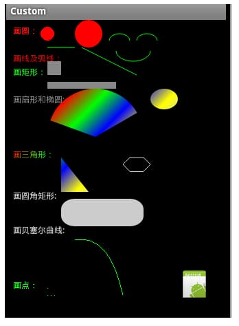
Androidはcanvasで様々な図形を描画します(点、線、弧、円、楕円、テキスト、矩形、多角形、曲線、角丸矩形)。
今回は、カスタムビュークラスを使用しています。
CustomActivity.java
public class CustomActivity extends Activity {
<未定義
オーバーライド
public void onCreate(Bundle savedInstanceState) { (パブリックボイドオンクリエイト)
<未定義
super.onCreate(savedInstanceState)を実行します。
setContentView(R.layout.main)を設定します。
init()を実行します。
}
private void init() {
    LinearLayout layout=(LinearLayout) findViewById(R.id.root);
    final DrawView view=new DrawView(this);
    view.setMinimumHeight(500);
    view.setMinimumWidth(300);
    //notify the view component to redraw
    view.invalidate();
    layout.addView(view);

}
}
重要なクラスカスタムViewコンポーネントは、ViewコンポーネントのonDraw(Canvase)メソッドをオーバーライドすることです。次のステップは、そのCanvasにたくさんのジオメトリ、ポイント、ライン、アーク、円、楕円、テキスト、長方形、ポリゴン、カーブ、丸い長方形、その他あらゆる種類の形を描くことです!このメソッドでは、Viewコンポーネントで描画されるすべてのジオメトリが表示されます。
DrawView.java
public class DrawView extends View { <未定義
public DrawView(Context context) {
    super(context);
}

@Override
protected void onDraw(Canvas canvas) {
    super.onDraw(canvas);

    // Create a paintbrush
    Paint p = new Paint();
    p.setColor(Color.RED);// set red

    canvas.drawText("DrawCircle:", 10, 20, p);// Draw text
    canvas.drawCircle(60, 20, 10, p);// small circle
    p.setAntiAlias(true);// Set the jagged effect of the brush. true is remove, you'll understand the effect when you see it
    canvas.drawCircle(120, 20, 20, p);// large circle

    canvas.drawText("Draw lines and arcs: ", 10, 60, p);
    p.setColor(Color.GREEN);// set green
    canvas.drawLine(60, 40, 100, 40, p);// draw a line
    canvas.drawLine(110, 40, 190, 80, p);// slash
    // draw the smiley arc
    p.setStyle(Paint.Style.STROKE);// set hollow
    RectF oval1=new RectF(150,20,180,40);
    canvas.drawArc(oval1, 180, 180, false, p);//small arc
    oval1.set(190, 20, 220, 40);
    canvas.drawArc(oval1, 180, 180, false, p);//small arc
    oval1.set(160, 30, 210, 60);
    canvas.drawArc(oval1, 0, 180, false, p);//small arc

    canvas.drawText("Draw Rectangle:", 10, 80, p);
    p.setColor(Color.GRAY);// set gray
    p.setStyle(Paint.Style.FILL);// set fill
    canvas.drawRect(60, 60, 80, 80, p);// square
    canvas.drawRect(60, 90, 160, 100, p);// rectangle

    canvas.drawText("Draw sectors and ellipses:", 10, 120, p);

    Shader mShader = new LinearGradient(0, 0, 100, 100,
            new int[] { Color.RED, Color.GREEN, Color.BLUE, Color.YELLOW,
                    Color.LTGRAY }, null, Shader.TileMode.REPEAT); // A material that creates a linear gradient along a line.
    p.setShader(mShader);
    // p.setColor(Color.BLUE);
    RectF oval2 = new RectF(60, 100, 200, 240); // set a new rectangle and scan the measurement
    canvas.drawArc(oval2, 200, 130, true, p);
    // draw arc, the first parameter is RectF: the class is the second parameter is the start of the angle, the third parameter is how many degrees, the fourth parameter is true when drawing a sector, is false when drawing an arc
    // draw ellipse, change the oval
    oval2.set(210,100,250,130);
    canvas.drawOval(oval2, p);

    canvas.drawText("Draw triangle: ", 10, 200, p);
    // draw this triangle, you can draw any polygon
    Path path = new Path();
    path.moveTo(80, 200);// this point is the starting point of the polygon
    path.lineTo(120, 250);
    path.lineTo(80, 250);
    path.close(); // make these points form a closed polygon
    canvas.drawPath(path, p);

    // You can draw a lot of arbitrary polygons, like the following hexagon
    p.reset();// reset
    p.setColor(Color.LTGRAY);
    p.setStyle(Paint.Style.STROKE);//set hollow
    Path path1=new Path();
    path1.moveTo(180, 200);
    path1.lineTo(200, 200);
    path1.lineTo(210, 210);
    path1.lineTo(200, 220);
    path1.lineTo(180, 220);
    path1.lineTo(170, 210);
    path1.close();//close
    canvas.drawPath(path1, p);


    //draw rounded rectangle
    p.setStyle(Paint.Style.FILL);//fill
    p.setColor(Color.LTGRAY);
    p.setAntiAlias(true);// set the jagged effect of the brush
    canvas.drawText("Draw rounded rectangle:", 10, 260, p);
    RectF oval3 = new RectF(80, 260, 200, 300);// set a new rectangle
    canvas.drawRoundRect(oval3, 20, 15, p);// the second parameter is the x-radius and the third parameter is the y-radius

    //draw a Bezier curve
    canvas.drawText("drawBezierCurve:", 10, 310, p);
    p.reset();
    p.setStyle(Paint.Style.STROKE);
    p.setColor(Color.GREEN);
    Path path2=new Path();
    path2.moveTo(100, 320);//Set the starting point of Path
}
OK!ははは
http://hi.baidu.com/chenjiaping10/item/e6b42cdd9b84130dd68ed05b
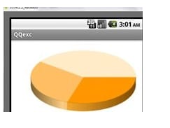
今日は、android:で円グラフを描く方法を紹介します。
セクターを描画するには
RectF oval2 = new RectF(60, 100, 200, 240)。
// 左上点の x 座標を 60、左上点の y 座標を 100、右下点の x 座標を 200、右下点の y 座標を 240 とする新しい矩形を設定します。
// 円弧を描く、第1引数はRectF:クラス 第2引数は角度の開始点、第3引数は何度、第4引数は真ならセクター、偽なら円弧になる
canvas.drawArc(oval2, 200, 130, true, p)を実行します。
I. ネットワークなし
Androidの描画APIでは円グラフを直接描画することができるため、セクタを描画してつなぎ合わせるという、より原始的な方法を用いました。立体感を出すために20回描画しているので、上下の位置を変えるたびに立体的に見えるプログラムになっている(もっといい方法があれば、教えてほしいということです)
canvas.drawArc(new RectF(0, 0, 300, 100), 0,60, true, paint)を実行します。
は、幅300、高さ100、水平に時計回りに60度のセクターを描きますが、これはプログラムが円グラフ全体を縫い合わせる方法です。
II. ネットワークを使って
Google APIを利用して実装。
WebView webView = new WebView(this);
String url = "http://chart.apis.google.com/chart?cht=p3&chs=350x180&chd=t:30,30,40";
webView.loadUrl(url)を実行します。
setContentView(webView)を設定します。
ここで、ct=p3はグラフの種類が円グラフ、chs=350x180は幅と高さ、chd=t:30,30,40は円グラフを3分割し、それぞれの割合を表示することを意味し、URL形式でGoogle APIにパラメータを渡しています。
返される結果は、パラメータに従って生成された円グラフ画像を含むWebページなので、AndroidコントロールのWebViewとして受け取り、表示します。
以下は結果画像です。
Androidはcanvasで様々な図形を描画します(点、線、弧、円、楕円、テキスト、矩形、多角形、曲線、角丸矩形)。
==========================================================
http://my.oschina.net/taisha/blog/71630
Canvasについてはすでに説明し、独自のViewを作成する方法を学びました。また、第7章ではMapViewのオーバーレイにCanvasを使用してラベル付けしました。
A canvas (Canvas) is a very common concept in graphics programming and usually consists of three basic drawing components.
Canvasは、基礎となるビットマップに基本的なグラフィックを描画する描画メソッドを提供します。
ペイント ブラシとも呼ばれ、ビットマップへの基本的なグラフィックの描画方法を指定することができます。
Bitmap 描画する面。
       The Android drawing API supports transparency, gradient fills, rounded rectangles, and anti-aliasing. Unfortunately, due to resource limitations, it does not yet support vector graphics, which use a traditional raster style of redrawing.
      This raster approach results in improved efficiency, but changing a Paint object does not affect the basic graphics already drawn, it only affects the new elements.

      Tip.
      If you have a Windows development background, Android's 2D drawing capabilities are roughly equivalent to those of GDI+.

   1. What can be drawn?

      The Canvas class encapsulates the bitmap used as the drawing surface; it also provides draw* methods to implement the design.

      The following list provides a brief description of the basic graphics available, but does not delve into the details of each of the draw methods.

      drawARGB / drawRGB / drawColor Fills the canvas with a single color.
      drawArc Draws an arc between the two corners of a rectangular area.
      drawBitmap Draws a bitmap on the canvas. You can change the appearance of the target bitmap by specifying the target size or by using a matrix.
      drawBitmapMesh Draws a bitmap using a mesh, which manipulates the appearance of the target by moving the points in the mesh.
      drawCircle draws a circle of the specified radius with the given point as the center.
      drawLine(s) Draws a line (multiple) between two points.
      drawOval Draws an ellipse with the specified rectangle as the boundary.
      drawPaint fills the entire Canvas with the specified Paint
      drawPath Draws the specified Path. path objects are often used to hold a collection of basic shapes in an object.
      drawPicture Draws a Picture object in the specified rectangle.
      drawPosText Draws a text string with the specified offset for each character.
      drawRect Draws a rectangle.
      drawRoundRect Draws a rectangle with rounded corners.
      drawText Draws a string of text on the Canvas. The text's font, size, and rendering properties are set in the Paint object used to render the text.
      drawTextOnPath draws the text on a specified path.
      drawVertices Draws a series of triangular facets, specifying them by a series of vertices.

      Each of these drawing methods requires a Paint object to be specified to render it. In the following sections, learn how to create and modify Paint objects to do most of the work in drawing.

   2. Getting Work Done from Paint

      The Paint class is the equivalent of a brush and a palette. It can choose how to use the draw method described above to render the basic shapes drawn on the canvas. By modifying the Paint object, you can control colors, styles, fonts, and special effects as you draw. At its simplest, setColor lets you choose the color of a Paint, while the style of the Paint object (controlled using setStyle) determines whether to draw the outline of the drawing object (STROKE), fill only every part (FILL), or do both (STROKE_AND_FILL)

      In addition to these simple controls, the Paint class also supports transparency, plus it can be modified by using a wide variety of shadows, filters and effects to provide a richer, more complex palette of brushes and paints.

      The Android SDK includes some very good examples that illustrate most of the features available in the Paint class. You can find them in the graphics subdirectory of the API demos at
sdk root folder]\samplesApiDemossrccomandroidGraphics
      In the following sections, some of these features will be learned and used. These sections simply list the effects they can achieve (e.g. gradients and edge relief) without going into detail about all the possible cases.

   Using transparency

       All colors in Android contain an opacity component (alpha channel).
       When creating a color, its alpha value can be defined using the argb or parseColor method, as follows.
Javaコードです。
// 赤色を使用し、50%透明にする
int opacity = 127;
int intColor = Color.argb(opacity, 255, 0, 0);
int parsedColor = Color.parseColor("#7FFF0000");
コピーコード
また、setAlpha メソッドを使用すると、既存の Paint オブジェクトの透明度を設定することができます。
Javaコードです。
// 色を50%透明にする
int opacity = 127;
myPaint.setAlpha(opacity)を実行します。
コードをコピーする
      Creating a color that is not 100% transparent means that any basic shapes drawn with it will be partially transparent-that is, all basic shapes drawn under it will be partially visible.

      Transparency effects can be used in any class or method that uses a color, including Paint, Shader, and Mask Filter.

   Shader introduction

      Derived classes of the Shader class can be created to allow Paint to fill drawing objects with multiple solid colors.

      The most common use of Shader is to define gradient fills; gradients are one of the best ways to add depth and texture to 2D images. android includes a Bitmap Shader and a Compose Shader, and also, three gradient Shaders.
      It would be pointless to try to describe the effect of drawing in words, so a look at the diagram should give you an idea of how each Shader works. From left to right, they are LinearGradient, RadialGradient and SweepGradient.
ヒント
      Not included is the ComposerShader, which creates a combination of multiple Shaders and BitmapShaders so that a drawing brush can be created on top of a bitmap image.

      To use a Shader when drawing, you can apply it to a Paint using the setShader method, as shown in the following code.
      Paint shaderPaint = new Paint();
      shaderPaint.setShader(myLinearGradient);


      Anything you paint with this Paint will be filled with the Shader you specify, not with the Paint's own color.
グラデーションシェーダーの定義
Using the Gradient Shader, as shown above, allows you to fill an image with alternating changing colors; you can define a color gradient as a simple alternation of two colors, as follows.
javaのコードです。
int colorFrom = Color.BLACK;
int colorTo = Color.WHITE。
LinearGradient linearGradientShader = new LinearGradient(x1, y1, x2, y2, colorFrom, colorTo, TileMode.CLAMP);
コードをコピーする
Alternatively, you can define more complex color sequences that are distributed according to a set scale, as shown in the following RadialGradientShader example.
javaのコードです。
int[] gradientColors = new int[3];
gradientColors[0] = Color;
gradientColors[1] = Color.YELLOW。
gradientColors[2] = Color;
float[] gradientPositions = new float[3]です。
gradientPositions[0] = 0.0f。
gradientPositions[1] = 0.5f。
gradientPositions[2] = 1.0f。
RadialGradient radialGradientShader = new RadialGradient(centerX,centerY, radius, gradientColors, gradientPositions, TileMode.CLAMP).TileMode.CLAMP は、グラデーションカラーとグラデーションポジションを指定します。
コードをコピーする
Each Gradient Shader (Linear, Radial, and Scanned) can use both of these techniques to define a gradient fill.
シェーダーTileModesの使用
タイルシェーダのブラシサイズは、境界のある矩形を使用して明示的に定義するか、中心点と半径の長さを使用して定義することができます。
       If the area defined by the Shader's brush is smaller than the area to be filled, then TileMode will determine what to do with the remaining area.
       CLAMP uses the Shader's border color to fill the remaining space.
       MIRROR Stretches the Shader image horizontally and vertically so that each image is stitched to the previous one.
       REPEAT Repeats the Shader image horizontally and vertically, but does not stretch it.
MaskFilterの使用
       The MaskFilter class allows you to assign an edge effect to a Paint.
       The following MaskFilter classes are included with Android.

       BlurMaskFilter specifies a blur style and radius to handle the edges of Paint.
       EmbossMaskFilter specifies the direction of the light source and the intensity of the ambient light to add embossing effects.

       To apply a MaskFilter, you can use the setMaskFilter method and pass it a MaskFilter object. The following example applies an EmbossMaskFilter to an existing Paint.
javaのコードです。
// 光源の向きを設定する
float[] direction = new float[] { 1, 1, 1 };
// 環境光の明るさを設定する
float light = 0.4f;
// 適用する反射のレベルを選択する
float specular = 6;
// マスクに一定レベルのぼかしを適用する
float blur = 3.5f;
EmbossMaskFilter emboss = new EmbossMaskFilter(direction,light,specular,blur);
// マスクを適用する myPaint.setMaskFilter(emboss)。
コードをコピーする
The FingerPaint API demo included in the SDK is a very good example of how to use MaskFilter. It shows the effect of both filters.
ColorFilterの使用
MaskFilter is a conversion of a Paint's alpha channel, while ColorFilter applies a conversion to each RGB channel. All classes derived from ColorFilter ignore the alpha channel when performing their conversions.
Androidには、3つのColorFilterが搭載されています。
    ColorMatrixColorFilter can specify a 4×5 ColorMatrix and apply it to a Paint. ColorMatrixes are commonly used in programs to perform processing on images, and they are useful because they support the use of matrix multiplication to perform link conversions.

     LightingColorFilter multiplies the RGB channel of the first color, and then adds the second color. The result of each conversion is limited to between 0 and 255.
     PorterDuffColorFilter can use any of the 16 Porter-Duff rules for digital image composition to apply a specified color to Paint.

    Apply a ColorFilter using the setColorFilter method, as follows.
    myPaint.setColorFilter(new LightingColorFilter(Color.BLUE, Color.RED));

     The ColorMatrixSample in the API is a very good example to illustrate how to use ColorFilter and Color Matrix.

     Using PathEffect

     So far, all effects affect the way Paint fills the image; PathEffect is used to control the way outlines (lines) are drawn.
PathEffects は、Path の基本図形を描画する際に特に有用ですが、任意の Paint に適用して、線の描画方法に影響を与えることも可能です。
     Using PathEffects, you can change the appearance of the corners of a shape and control the appearance of the outline. android includes several PathEffects, including.
     CornerPathEffect allows you to smooth the sharp corners of a basic shape by using rounded corners instead of sharp ones.
DashPathEffect DashPathEffect を使用すると、実線の代わりに破線の輪郭(短い水平線/点)を作成することができます。また、破線/実線の線分の繰り返しパターンを任意に指定することができます。
   DiscretePathEffect is similar to DashPathEffect, but with added randomness. When drawing it, you need to specify the length of each segment and how far it deviates from the original path.

   PathDashPathEffect This effect defines a new shape (path) and uses it as an outline marker for the original path.
   The following effects can be used in combination with multiple Path Effects in a single Paint.

   SumPathEffect adds two effects to a path sequentially so that each effect can be applied to the original path and the two results can be combined.

   ComposePathEffect applies two effects together, using the first effect first and then applying the second effect on top of this effect.
   Changes in the PathEffect of an object shape affect the area of the shape. This ensures that the fill effect applied to the same shape will be drawn to the new boundary.

   The PathEffect can be applied to the Paint object using the setPathEffect method, as shown below:
javaのコードです。
borderPaint.setPathEffect(new CornerPathEffect(5));
コードをコピーする
The PathEffect API example gives instructions on how to apply each effect.
Xfermodeを変更する
   You can modify Paint's Xfermode to affect the way new colors are drawn on top of an existing Canvas image.
   Under normal circumstances, drawing on top of an existing image will add a new layer of shapes on top of it. If the new Paint is completely opaque, then it will completely obscure the Paint below it; if it is partially transparent, then it will be colored with the color below it.

   The following Xfermode subclasses can change this behavior.
   AvoidXfermode specifies a color and tolerance that forces Paint to avoid drawing over it (or only draw over it).
   PixelXorXfermode applies a simple pixel XOR operation when overriding an existing color.
   PorterDuffXfermode This is a very powerful transformation mode, using which any of the 16 Porter-Duff rules for image composition can be used to control how Paint interacts with an existing Canvas image.

   To apply the transformation mode, you can use the setXferMode method, as follows.
javaのコードです。
AvoidXfermode avoid = new AvoidXfermode(Color.BLUE, 10, AvoidXfermode.Mode. AVOID); borderPen.setXfermode(avoid);
コードをコピーする
-
アンチエイリアス効果による画質向上
When drawing a new Paint object, you can influence the way it is rendered by passing it some flags, and ANTI_ALIAS_FLAG is one of those interesting flags that ensures that an anti-aliasing effect is used to smooth out the appearance of the slash when it is drawn.

The anti-aliasing effect is especially important when drawing text, as the text is very easy to read after the anti-aliasing effect is applied. To create a smoother text effect, you can apply SUBPIXEL_TEXT_FLAG, which will apply a sub-pixel anti-aliasing effect.

These markers can also be set manually using the setSubpixelText and setAntiAlias methods, as follows.
javaのコードです。
myPaint.setSubpixelText(true);
myPaint.setAntiAlias(true);
コードをコピーする
2Dグラフィックスのハードウェアアクセラレーション
   In the current age of 2D graphics enthusiasts everywhere, Android allows you to use hardware acceleration to render your app.

   If the device can use hardware acceleration, then by setting this flag you can make hardware rendering available for every View in the activity. Although it reduces the load on the system handler, while it greatly increases the speed of image processing, hardware acceleration has a corresponding negative effect.

   Hardware acceleration can be turned on in your activity by applying the Window.FEATURE_OPENGL flag using the requestWindowFeature method, as follows.
javaのコードです。
myActivity.requestWindowFeature(Window.FEATURE_OPENGL);
コードをコピーする
   Not all 2D drawing base graphics in Android are supported by hardware (especially most of the PathEffects described earlier).

   At the same time, since the entire activity is actually rendered as a Canvas, an invalid request for any View will cause the entire activity to be redrawn.
キャンバス描画のベストプラクティス・レッスンラーンド
   2D self-drawing operations are very resource-intensive for handlers; inefficient drawing methods can block GUI threads and adversely affect the application's response. This is even more realistic for resource-constrained environments where there is only one handler.

   Attention needs to be paid here to the resource consumption of the onDraw method and the CPU cycles consumed so that an attractive looking application is not made completely unresponsive.

    There are a number of techniques available to help minimize the resource consumption associated with self-drawing controls. We are not concerned with general principles, but rather with certain Android-specific considerations so that you can ensure that you can create activities that look sleek and that remain interactive (note that this list below is not complete).

   Consider hardware acceleration OpenGL hardware acceleration support for 2D graphics is excellent, so you should always consider whether it is appropriate for your activity. Another superior approach is to compose the activity with only a single View and rapid, time-consuming updates. Always make sure that the basic graphics you use can be supported by the hardware.

   Consider size and orientation When designing Views and layouts, be sure to consider (and test) how they will look at different resolutions and sizes.

   Create static objects only once The creation of objects in Android is quite expensive. Therefore, where possible, apps only create drawing objects like Paint objects, Paths and Shaders once, rather than re-creating them every time the View is invalidated.

   Remember that onDraw is very resource intensive Executing the onDraw method is very resource intensive processing and it forces Android to perform multiple image combination and bitmap building operations. Here are a few suggestions for modifying the appearance of the Canvas without redrawing it.

   Use Canvas transformations You can use transformations like rotate and translate to simplify the complex related position of elements in Canvas. For example, instead of placing and rotating each text element around a dial, you can simply rotate the canvas by 22.5? and then draw the text in the same position.

   Using animation Consider using animation to perform a pre-set transformation of the View instead of manually redrawing it. Scaling, rotation and transformation animations can be performed in the active View and can provide a way to provide scaling, rotation or dithering effects in a way that makes efficient use of resources.

   Consider using bitmaps and 9 patches If the View uses a static background, then you should consider using an image such as a bitmap or 9 patch rather than redrawing it manually.
高度なコンパスダイヤルの例
   A simple compass has been created. In the previous chapter, you went back to this example and extended it so that it could use the accelerometer hardware to display horizontal and vertical directions.

   The UI in those examples is simple enough to ensure that the code in those chapters is as clear as possible.

   In the following example, some important changes are made to CompassView's onDraw method to turn it from a simple, flat compass into a dynamic artificial horizon, as shown in the figure.
Androidはcanvasを使って様々な図形(点、線、弧、円、楕円、テキスト、長方形、多角形、曲線、角丸長方形)を描くことができる。
上の画像は白黒なので、実際に手を動かしてこのコントロールを作成しないと、その効果を十分に発揮することはできません。
(1) まず、リソースファイルcolors.xmlを修正して、ボーダー、文字盤の影、空と地の色の値を含めます。また、ボーダーと文字盤のマーカーに使用されている色も更新します。
javaのコードです。
<?xml version="1.0" encoding="utf-8"? >
<resources>
<color name="text_color">#FFFF</color>
<color name="background_color">#F000</color>
<color name="marker_color">#FFFF</color>
<color name="shadow_color">#7AAA</color>
<color name="outer_border">#FF444444</color>
<color name="inner_border_one">#FF323232</color>
<color name="inner_border_two">#FF414141</color>
<color name="inner_border">#FFFFFFFF</color>
<color name="horizon_sky_from">#FFA52A2A</color>
<color name="horizon_sky_to">#FFFFC125</color>
<color name="horizon_ground_from">#FF5F9EA0</color>
<color name="horizon_ground_to">#FF00008B</color>
</resources>
コピーコード
(2) 空中地平線の空と地として使われるPaintとShaderオブジェクトは、現在のViewのサイズに基づいて作成されるため、作成中のPaintオブジェクトのように静的であることはできません。そのため、Paintオブジェクトは作成されなくなり、代わりにそれらが使用するグラデーション配列と色が構築されます。
javaのコードです。
int[] borderGradientColors;
float[] borderGradientPositions;
int[] glassGradientColors;
float[] glassGradientPositions;
int skyHorizonColorFrom;
int skyHorizonColorTo;
int groundHorizonColorFrom;
int groundHorizonColorTo;
コピーコード
(3) CompassViewのinitCompassViewメソッドを更新し、(1)で作成したリソースを使用して、(2)で作成した変数を初期化します。既存のメソッドのコードはほとんどそのままで、textPaint、circlePaint、markerPaintの変数を以下のように少し変更するだけでよいです。
javaのコードです。
protected void initCompassView() {
setFocusable(true);
// Get external resources
Resources r = this.getResources();
circlePaint = new Paint(Paint.ANTI_ALIAS_FLAG);
circlePaint.setColor(R.color.background_color);
circlePaint.setStrokeWidth(1);
circlePaint.setStyle(Paint.Style.STROKE);
northString = r.getString(R.string.cardinal_north);
eastString = r.getString(R.string.cardinal_east);
southString = r.getString(R.string.cardinal_south);
westString = r.getString(R.string.cardinal_west);
textPaint = new Paint(Paint.ANTI_ALIAS_FLAG);
textPaint.setColor(r.getColor(R.color.text_color));
textPaint.setFakeBoldText(true);
textPaint.setSubpixelText(true);
textPaint.setTextAlign(Align.LEFT);
textHeight = (int)textPaint.measureText("yY");
markerPaint = new Paint(Paint.ANTI_ALIAS_FLAG);
markerPaint.setColor(r.getColor(R.color.marker_color));
markerPaint.setAlpha(200);
markerPaint.setStrokeWidth(1);
markerPaint.setStyle(Paint.Style.STROKE);
markerPaint.setShadowLayer(2, 1, 1, r.getColor(R.color.shadow_color));
コードをコピーする
a. Create the array of colors and positions used by the Radial Shader to draw the outer boundaries.
javaのコードです。
borderGradientColors = new int[4];
borderGradientPositions = new float[4];
borderGradientColors[3] = r.getColor(R.color.outer_border);
borderGradientColors[2] = r.getColor(R.color.inner_border_one);
borderGradientColors[1] = r.getColor(R.color.inner_border_two);
borderGradientColors[0] = r.getColor(R.color.inner_border);
borderGradientPositions[3] = 0.0f;
borderGradientPositions[2] = 1-0.03f;
borderGradientPositions[1] = 1-0.06f;
コードをコピーする
b. Now create the radial gradient color and position arrays, which will be used to create the translucent "glass dome" (glass dome), which is placed on top of the View, thus giving the illusion of depth.
javaのコードです。
glassGradientColors = new int[5];
glassGradientPositions = new float[5];
int glassColor = 245;
glassGradientColors[4]=Color.argb(65,glassColor,glassColor, glassColor);
glassGradientColors[3]=Color.argb(100,glassColor,glassColor,glassColor);
glassGradientColors[2]=Color.argb(50,glassColor,glassColor, glassColor);
glassGradientColors[1]=Color.argb(0,glassColor,glassColor, glassColor);
glassGradientColors[0]=Color.argb(0,glassColor,glassColor, glassColor);
glassGradientPositions[4] = 1-0.0f;
glassGradientPositions[3] = 1-0.06f;
glassGradientPositions[2] = 1-0.10f;
glassGradientPositions[1] = 1-0.20f;
glassGradientPositions[0] = 1-1.0f;
コードをコピーする
c. Finally, get the colors used to create the linear color gradients that will be used to represent the sky and ground in the aerial horizon.
javaのコードです。
skyHorizonColorFrom = r.getColor(R.color.horizon_sky_from);
skyHorizonColorTo = r.getColor(R.color.horizon_sky_to);
groundHorizonColorFrom = r.getColor(R.color.horizon_ground_from);
groundHorizonColorTo = r.getColor(R.color.horizon_ground_to);
コードをコピーする
(6) 円の各部分(地面と空)を埋めるために使用するパスを作成します。各パーツのスケールは、形式化後にピッチ値に関連付ける必要があります。
javaのコードです。
パス skyPath = new Path();
skyPath.addArc(innerBoundingBox, -tiltDegree, (180 + (2 * tiltDegree))) を実行します。
コードをコピーする
(7) Rotate the Canvas around the center of the circle in the opposite direction of the current flip angle, and use the Paint created in step (4) to draw the sky and ground paths.
javaのコードです。
canvas.rotate(-rollDegree, px, py)を実行します。
canvas.drawOval(innerBoundingBox, groundPaint)を実行します。
canvas.drawPath(skyPath,skyPaint)。
canvas.drawPath(skyPath, markerPaint)を実行します。
コードをコピーする
(8) The next step is the disk marker, first calculating the start and end points of the horizontal horizontal marker.
javaのコードです。
int markWidth = radius / 3; int startX = center.x - markWidth; int endX = center.x + markWidth;
コピーコード
(9) To make the horizontal values easier to read, you should make sure that the pitch angle scale always starts from the current value. The following code calculates the position of the interface between the sky and the ground on the horizontal plane.
javaのコードです。
double h = innerRadius*Math.cos(Math.toRadians(90-tiltDegree)); double justTiltY = center.y - h.です。
コードをコピーする
(10) Find the number of pixels that represent each tilt angle.
javaのコードです。
float pxPerDegree = (innerBoundingBox.height()/2)/45f;
コードをコピーする
(11) Now traverse 180 degrees to give a sliding scale of possible pitch angles, centered on the current tilt value.
javaのコードです。
for (int i = 90; i >= -90; i -= 10) {.
<未定義
double ypos = justTiltY + i*pxPerDegree;
// 内側の文字盤の目盛りだけを表示する
if ((ypos < (innerBoundingBox.top + textHeight)) || (ypos > innerBoundingBox.bottom - textHeight)) continue;
// 各スケール増分の直線と傾斜角度を描画する
canvas.drawLine(startX, (float)ypos, endX, (float)ypos, markerPaint);
t displayPos = (int)(tiltDegree - i);
文字列 displayString = String.valueOf(displayPos)。
float stringSizeWidth = textPaint.measureText(displayString)。
canvas.drawText(displayString, (int)(center.x-stringSizeWidth/2), (int)(ypos)+1, textPaint)を実行します。
}
コピーコード
(12) Now, draw a thicker line at the earth/sky interface. Before drawing the line, change the line thickness of the markerPaint object (and then set it back to the previous value).
javaのコードです。
markerPaint.setStrokeWidth(2)を実行します。
canvas.drawLine(center.x - radius / 2, (float)justTiltY, center.x + radius / 2, (float)justTiltY, markerPaint)を実行します。
markerPaint.setStrokeWidth(1)。
コードをコピーする
   (13) To make it easier for the user to read the exact flip value, an arrow should be drawn and a text string should be displayed to represent the exact value.

   Create a new Path and use the moveTo/lineTo methods to construct an open arrow that points ahead of a straight line. Then draw the path and a text string to show the current flip.
javaのコードです。
// 矢印を描く
Path rollArrow = new Path();
rollArrow.moveTo(center.x - 3, (int)innerBoundingBox.top + 14)を実行します。
rollArrow.lineTo(center.x, (int)innerBoundingBox.top + 10)を実行します。
rollArrow.moveTo(center.x + 3, innerBoundingBox.top + 14)を実行します。
rollArrow.lineTo(center.x, innerBoundingBox.top + 10)を実行します。
canvas.drawPath(rollArrow,markerPaint)を実行します。
// 文字列を描画する
String rollText = String.valueOf(rollDegree)とする。
double rollTextWidth = textPaint.measureText(rollText)。
canvas.drawText(rollText, (float)(center.x - rollTextWidth / 2), innerBoundingBox.top + textHeight + 2, textPaint)を実行します。
コードをコピーする
(14) Rotate the Canvas just above so that you can draw the rest of the disk markers.
javaのコードです。
canvas.restore()を実行します。
コピーコード
(15) Rotate the Canvas 10 degrees at a time, then draw a marker or a value until you finish drawing the flipped value dial. When finished with the dial, return the Canvas to the orientation directly above.
javaのコードです。
canvas.save()を実行します。
canvas.rotate(180, center.x, center.y)を実行します。
for (int i = -180; i < 180; i += 10) {.
<未定義
// 30度ごとに数値を表示する
if (i % 30 == 0) { { { { i % 30 == 0
<未定義
String rollString = String.valueOf(i*-1);
float rollStringWidth = textPaint.measureText(rollString)。
PointF rollStringCenter = new PointF(center.x-rollStringWidth / 2, innerBoundingBox.top+1+textHeight);
canvas.drawText(rollString, rollStringCenter.x, rollStringCenter.y, textPaint)を実行します。
}
// そうでない場合は、マーカー線を引く
else { canvas.drawLine(center.x, (int)innerBoundingBox.top, center.x, (int)innerBoundingBox.top + 5, markerPaint).Line(center.x, (int)innerBoundingBox.top + 5, markerPaint);
}
canvas.rotate(10, center.x, center.y)を実行します。
}
canvas.restore()を実行します。
http://www.jcodecraeer.com/a/anzhuokaifa/androidkaifa/2012/1224/738.html
Androidの描画:直線を描くためのdrawLineメソッド
機能説明】直線の両端の座標を指定して、キャンバス上に直線を描画します。このメソッドは1本の直線しか描画できないので、同時に複数の直線を描画する必要がある場合は、drawLinesメソッドを使用します。
[基本構文】 public void drawLine (float startX, float startY, float stopX, float stopY, Paint paint)
パラメータ説明
startX: スタートエンドポイントのX座標。
startY: 始点のY座標。
stopX: 終了する終点のX座標。
stopY: 終了する終点のY座標.
paint: 線を描くのに使用するブラシ。
例】次のコードは、キャンバスに直線を引く方法を示しています。
protected void onDraw(Canvas キャンバス) { {...
<未定義
// TODO 自動生成されるメソッドスタブ
super.onDraw(canvas)を実行します。
mPaint.setColor(Color.BLACK); //ブラシの色を設定します。
canvas.drawColor(Color.WHITE); //背景色を設定します。
mPaint.setStrokeWidth((float) 1.0); //線幅を設定します。
canvas.drawLine(50, 50, 450, 50, mPaint); //線を描画します。
mPaint.setStrokeWidth((float) 5.0); //線幅を設定します。
canvas.drawLine(50, 150, 450, 150, mPaint); //線を描画します。
mPaint.setStrokeWidth((float) 10.0); //線幅を設定します。
canvas.drawLine(50, 250, 450, 250, mPaint); //線を描画します。
mPaint.setStrokeWidth((float) 15.0); //線幅を設定します。
canvas.drawLine(50, 350, 450, 350, mPaint); //線を描画します。
mPaint.setStrokeWidth((float) 20.0); //線幅を設定します。
canvas.drawLine(50, 450, 450, 450, mPaint); //線を描画する
}
各直線は線幅が異なります。
関連
-
AndroidでFragmentを使用すると、Fragmentの内部コントロールを取得できず、findViewById()の結果がNullになる - 解決済み
-
アプリケーションがメインスレで仕事をしすぎている可能性がある
-
Androidのellipsizeプロパティ(余分なテキストは楕円で表示される)
-
Android LayoutInflaterの原則の分析は、ビュー(a)のステップの深い理解によってあなたのステップを取る
-
アンドロイドバージョン一覧
-
アンドロイドプログレスバー自定义
-
Androidの内部育成に磨きをかける2年間
-
Android Studio精彩案例(七)《ToolBar使用详解<一>》
-
app'の実行エラーです。ターゲットデバイスが見つかりませんでした。
-
アンドロイドについて:DescendantFocusability いくつかの使用感
最新
-
nginxです。[emerg] 0.0.0.0:80 への bind() に失敗しました (98: アドレスは既に使用中です)
-
htmlページでギリシャ文字を使うには
-
ピュアhtml+cssでの要素読み込み効果
-
純粋なhtml + cssで五輪を実現するサンプルコード
-
ナビゲーションバー・ドロップダウンメニューのHTML+CSSサンプルコード
-
タイピング効果を実現するピュアhtml+css
-
htmlの選択ボックスのプレースホルダー作成に関する質問
-
html css3 伸縮しない 画像表示効果
-
トップナビゲーションバーメニュー作成用HTML+CSS
-
html+css 実装 サイバーパンク風ボタン
おすすめ
-
BindView 問題 NULLオブジェクト参照で仮想メソッド 'void android ...' を呼び出そうとする
-
jniとjavaの間でbytearrayを受け渡しする
-
Android Studioの解決策:xxxは囲むクラスではありませんエラー
-
Android StudioでJavaファイルが認識されない問題を解決(赤いJが表示される)。
-
ArrayAdapter のソリューションでは、リソース ID が TextView である必要があります。
-
Androidにおけるメッセージの仕組みの分析 - 解決策。ビュー階層を作成した元のスレッドだけが、そのビューに触れることができる。
-
ConstraintLayoutにおけるChainとGuidelineの利用について
-
Android Studioのインポートプロジェクトが表示されます。ファイルをクランチするのに失敗しました
-
android.content.res.Resources$NotFoundException: 文字列リソースID #0x1
-
android.content.res.Resources$NotFoundException: 文字列リソースID #0x1エラー